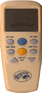
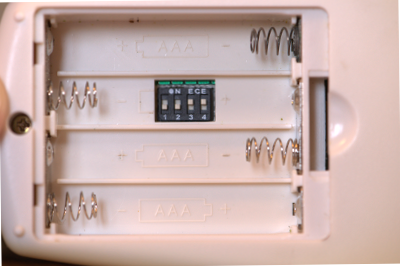
 For my first HackRF project, I thought I’d try to create a replacement for the remote controls used by my two Hampton Bay ceiling fans. First, we’ll have to understand how the remote communicates with the fan, which is what we’ll do in this post. These remotes let you control the light level and fan speed. The other features, like timers and temperature-based fan speed, are all processed on the remote itself; it just tells the fan the speed and light level to use. There are four dip switches under the batteries that let you “pair” the remote with an individual fan.
To find the remote’s transmit frequency, I looked up its FCCID on the FCC’s website, which told me it uses 303.85Mhz. With that knowledge, I used hackrf_transfer to record a sample of the remote telling the fan to go to “high” with the lights turned off. The command I used is as follows:
hackrf_transfer -r fan_high.iq -f 303000000 -s 8000000 -b 1
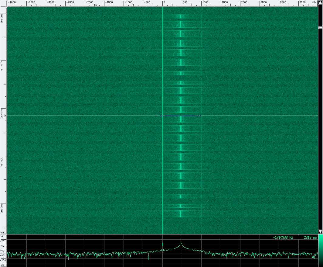
 After it was running, I pressed the button on the remote to turn the fan on, waited a moment, and stopped the recording. I opened the file in baudline as a “raw” file, with a sample rate of 8000000, 2 channels, quadrature and flip complex checked, using a an 8-bit signed decode format. Some older blog posts will claim that the data is unsigned, but that was changed in more recent firmware updates.
Looking at the signal in baudline’s waterfall view, you can see some kind of simple modulation going on. The transmission is broken up into short (~300 microsecond) and long (~600 microsecond) pulses, with a ~300 microsecond pause between each pulse. It looks a lot like binary to me. I assumed (correctly) that a short line was a 0, and a long line was a 1. It’s not shown below, but the remote actually transmits this pattern several times, with a delay between each packet.
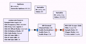
Now that we know that the signal looks like, I made a quick flowgraph in gnuradio companion for analysis. I didn’t want to perform the above steps, reopening the file in baudline every time I wanted to try a different setting on the remote. The graph listens on the remote’s frequency, and then uses the AM Demod block and a WX GUI Scope Sink to show the signal.
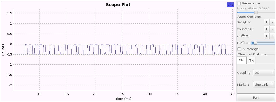
With the flowgraph running, I can see the waveform immediately, and examine the individual bits after each button press. You’ll need to turn off autorange, and increase your seconds/counts per division until something useful appears. After pressing a button on the remote, pause the scope to see the packet.
Next, I made small configuration changes on the remote, just to see which bits would change for a particular setting. By analyzing the remote in a lot of different states and recording my findings, I was able to determine where each setting was in the packet, and how to interpret it.
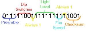
The preamble is consistent for every single packet, so no big mystery there. The dip switch bits correspond directly to the physical switches, albeit reversed: the left-most switch controls the right-most bit. The lowest light level the remote would transmit was a 22 (010110), and the highest was a 62 (111110). A 63 (111111) turns off the light completely. The two fan speed bits represent low (00), medium (01), high (10), and off (11). Two of the bits are mysteriously always set to 1 in every combination that I’ve tried, so we’ll just ignore those. The checksum was easy to recognize: it varied wildly with different settings, but was consistent when the same settings were used.
So now we know basically how to talk to the fan. To actually send a packet, we’ll need to know how to compute the checksum, but more on that next time. In the next post, we’ll build a class in C++ to generate the actual packet structure.
You are an amazing coder!!!!!!!!!!!!!!!!!!!!!
I went through this post step-by-step and was able to reproduce everything using my VW key fob. Nice work! I’m looking forward to parts 2 and 3.
I’m working on a something similar, except it involves infrared remotes and RF-based “remote extenders”. Put me in the same camp as Trent (looking forward to parts 2 and 3).