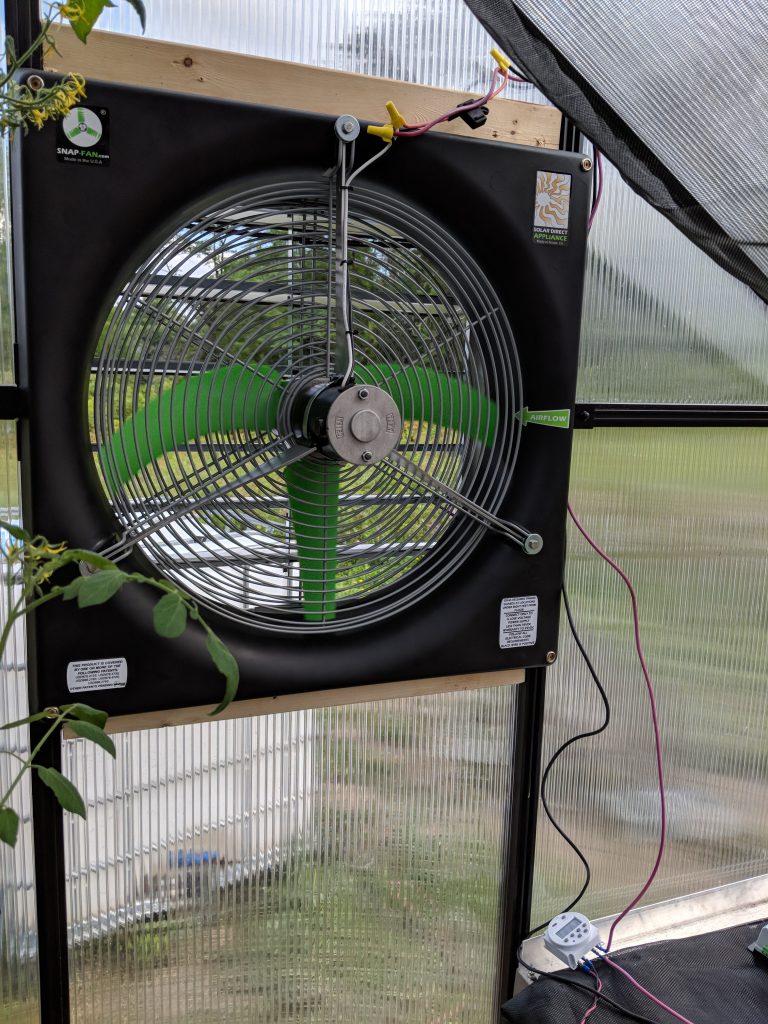
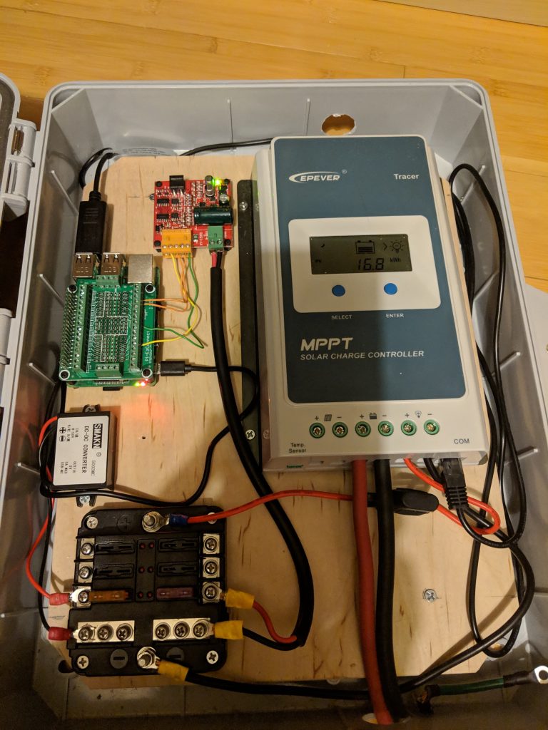
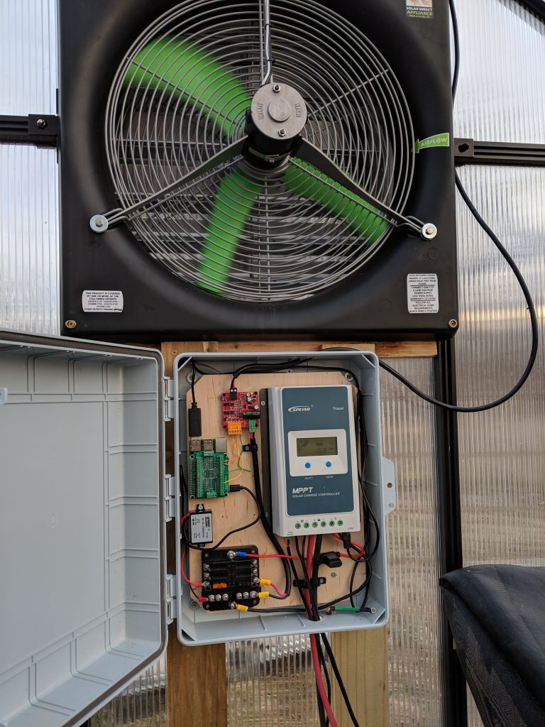
In part one, we put together the basic hardware for our solar-powered, Pi-controlled, greenhouse fan. This time, we’ll look at how to actually control the fan with Python on a Raspberry Pi.
Preparing the Raspberry Pi
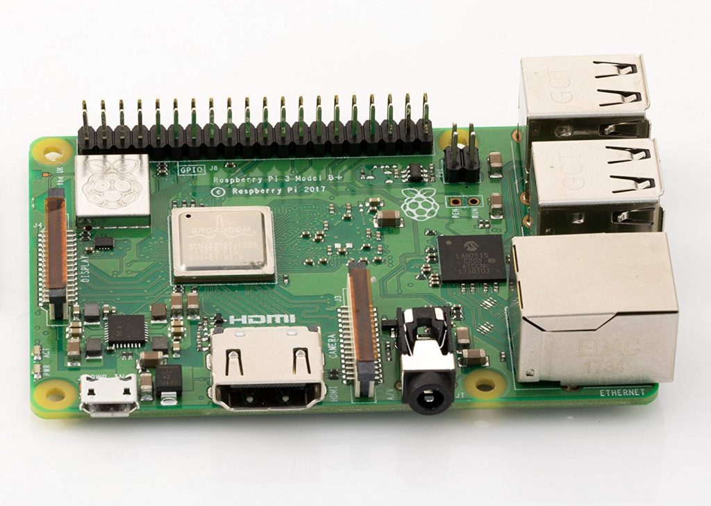
There are plenty of resources online about getting up and running with a Pi, and that’s not really my objective here, but I’ll describe the high-level steps. I used the Raspbian Lite image, though other distributions can work as well. Installing it is just a matter of writing the image to an SD card, adding an empty ‘ssh’ file to the boot partition to turn on SSH, connecting it to Ethernet, and SSH’ing in. Once you’re connected, you can configure WiFi and unplug the cable.
The Motor Controller
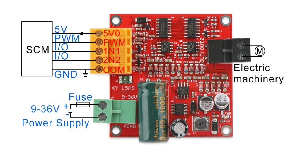
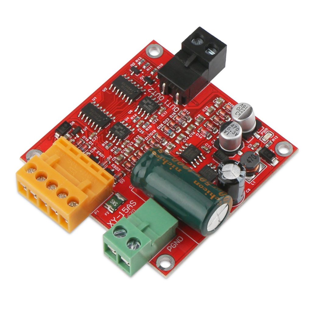
Using the motor controller itself is pretty simple. The Pi controls it through pins on the yellow connector, it’s powered through the green connector, and it connects to the motor with the black connector.
The yellow connector has 5 pins: a 5V power supply (the Pi documentation says that we more than the 0.5a it can provide, so we can’t use it to power our Pi), three I/O pins, and a ground. The I/O pins are control the state of the motor as described in the following table:
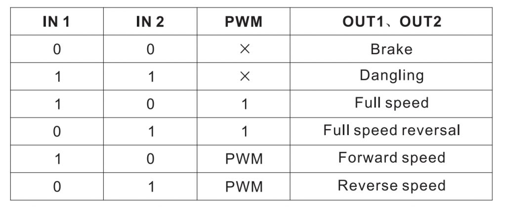
By controlling the power supplied to IN1 and IN2, we can switch between braking, dangling (spinning freely), forwards, and backwards. For example, if IN1 and IN2 both have power, the motor is off, but if we turn on IN1 and turn off IN2, the fan will spin forward. The PWM pin, described more below, is used to control the speed, if used. If it’s not used, it can just be directly connected to power so that it’s effectively always set to full-speed.
Controlling the Fan State
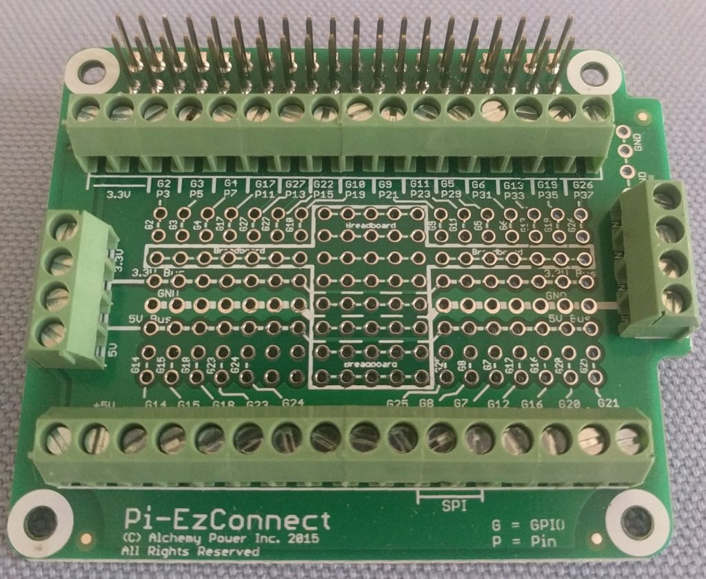
The Raspberry Pi has a number of GPIO (general purpose input/output) pins. Essentially, each pin can be set to either input, where we can read if there is power on the pin, or output, where we can supply power on the pin (or not). GPIO on the Pi works at 3.3 volts, so you’ll need to make sure any devices you want to use can accept that voltage. Some require 5 volts, for example. The motor controller we’re using operates from 3-5 volts, so we’re good!
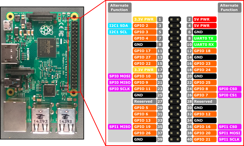
First, we’ll control the motor without speed control. I connected the motor controller’s IN1 and IN2 terminals to GPIO 12 and 16, respectively. Here is some Python using the wiringpi library to control the fan speed. Running it will cause the fan to spin forward at full speed.
#!/usr/bin/env python3
import wiringpi

fwd_pin = 12 # IN1
bwd_pin = 16 # IN2

def fwd():
    '''
    Make the motor spin forwards
    '''
    wiringpi.digitalWrite(fwd_pin, 1)
    wiringpi.digitalWrite(bwd_pin, 0)

def bwd():
    '''
    Make the motor spin backwards
    '''
    wiringpi.digitalWrite(fwd_pin, 0)
    wiringpi.digitalWrite(bwd_pin, 1)

def off():
    '''
    Turn of the motor (dangling)
    '''
    wiringpi.digitalWrite(fwd_pin, 1)
    wiringpi.digitalWrite(bwd_pin, 1)

def brake():
    '''
    Brake the motor
    '''
    wiringpi.digitalWrite(fwd_pin, 0)
    wiringpi.digitalWrite(bwd_pin, 0)

# Initialize the wiringPi library
wiringpi.wiringPiSetupGpio()

# Set both of our pins into output mode
wiringpi.pinMode(fwd_pin, 1)
wiringpi.pinMode(bwd_pin, 1)

# Turn on the fan
fwd()
Speed Control with PWM
Pulse-width modulation, briefly, controls the percentage of time that the pin is on, called the “duty cycle”. If the pin is high half the time, the duty cycle is 50%. The rate of these pulses is the frequency. You can picture this as a square wave. In this case, you don’t really need to know too much about PWM to use it.
The Raspberry Pi’s hardware can generate a PWM signal on GPIO 18, so that’s what we’ll use. We’ll connect GPIO 18 to the PWM input on the motor controller, and modify the above code. The motor controller’s manual suggests a 20khz signal, so we’ll aim for that. Here’s a snippet of code showing the PWM setup on the Pi:
pwm_pin = 18 # GPIO 18 supports hardware PWM
clock = 4    # Must be at least 2
max_range = 240  # 19200000 / 4 / 240 = 20000 (20khz)

# Just for verification
# It's not actually required that we calculate this.
freq = 19200000 / clock / max_range
print("Frequency:", freq)

# Configure PWM on our pin
wiringpi.pinMode(pwm_pin, 2)
wiringpi.pwmSetMode(wiringpi.PWM_MODE_MS)
wiringpi.pwmSetClock(clock)
wiringpi.pwmSetRange(max_range)

# Actually start the PWM signal at 50%
duty = 120
wiringpi.pwmWrite(pwmPin, duty)
The formula for calculating PWM frequency on the Pi is 19200000 / clock / range. The ‘range’ supplied is the maximum value that can supplied to pwmWrite(), so with the above code we can set the duty anywhere from 0 to 240. We’ve hardcoded the value 120, which will run the fan at 50%.
Here’s a more complete version, one that allows us to specify a percentage on the command line:
#!/usr/bin/env python3

import wiringpi
import sys

fwd_pin = 12
bwdPin = 16
pwmPin = 18
clock = 4    # Must be at least 2
max_range = 240  # 20khz

# Sanity checks
if clock < 2:
    print("Clock must be at least 2")
    exit(1)

if len(sys.argv) < 2:
    print("Usage: %s <Duty Percent>" % sys.argv[0])
    exit(1)

#
# Our control functions
#

def fwd():
    '''
    Make the motor spin forwards
    '''
    wiringpi.digitalWrite(fwd_pin, 1)
    wiringpi.digitalWrite(bwd_pin, 0)

def bwd():
    '''
    Make the motor spin backwards
    '''
    wiringpi.digitalWrite(fwd_pin, 0)
    wiringpi.digitalWrite(bwd_pin, 1)

def off():
    '''
    Turn of the motor (dangling)
    '''
    wiringpi.digitalWrite(fwd_pin, 1)
    wiringpi.digitalWrite(bwd_pin, 1)

def brake():
    '''
    Brake the motor
    '''
    wiringpi.digitalWrite(fwd_pin, 0)
    wiringpi.digitalWrite(bwd_pin, 0)

# Setup wiringpi and GPIO
wiringpi.wiringPiSetupGpio()
wiringpi.pinMode(fwd_pin, 1)
wiringpi.pinMode(bwd_pin, 1)

# Convert the requested percentage to
# a value between 0 and 'range' (240)
duty = int(max_range * (int(sys.argv[1]) / 100))

# If 0 is given, just turn it off.
if duty == 0:
    off()
    sys.exit(0)

# Configure PWM
wiringpi.pinMode(pwm_pin, 2)
wiringpi.pwmSetMode(wiringpi.PWM_MODE_MS)
wiringpi.pwmSetClock(clock)
wiringpi.pwmSetRange(max_range)
wiringpi.pwmWrite(pwm_pin, duty)

# Enable power
fwd()
Next time, we’ll add a temperature sensors to control the fan automatically.