In this project, I’m using a solar panel to charge a 12v Marine/RV battery, which will power a Raspberry Pi and an exhaust fan for an off-the-grid greenhouse. My first goal was just to have an exhaust fan that keeps the temperature in the 80-85°F range, but it’d also be cool to add a web interface for climate and power stats, automatically control lights, water plants, etc. First, we’ll just start off with the exhaust fan.
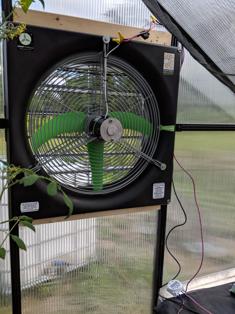
The first thing we needed was a fan. I installed a 20″ DC Snap-Fan with the help of my father-in-law. It operates on 12 to 24 volts, with more speed as the voltage increases. To test it out, we just hooked it up to a small timer and a 12 volt battery. (The fan blades look strange in the photo because it’s running.) With the timer in place, the fan would stupidly run during the daytime, no matter the temperature. Time to make it smarter!
The Pieces

An enclosure. This is just a nice box to house all of our electrical components.
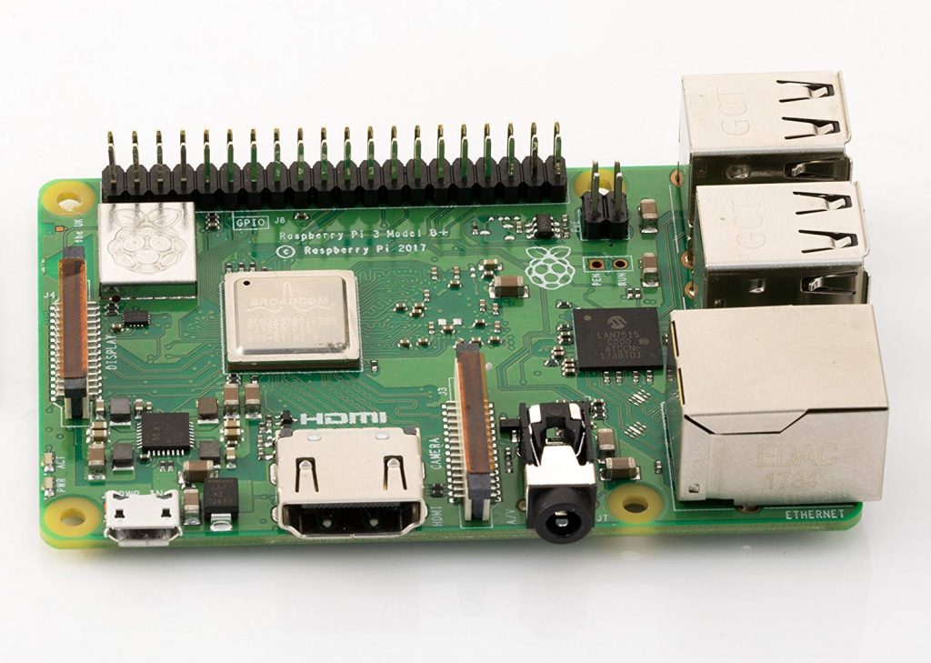
A Raspberry Pi to act as the brains. Mainly we need it for WiFi and GPIO (general purpose I/O), but they also have USB, HDMI, a GPU, and they’re fairly cheap.
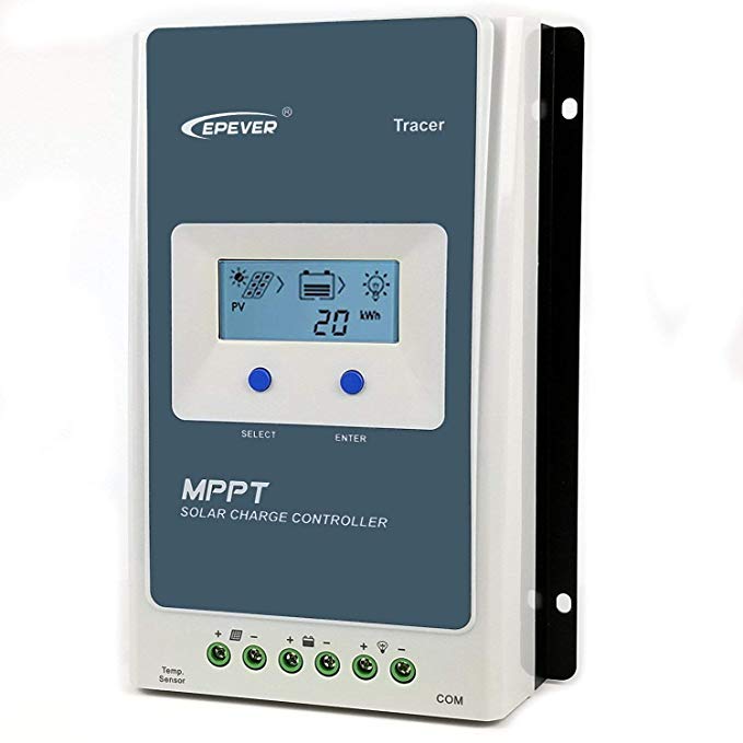
A MPPT solar charge controller to charge the battery. This connects to a solar panel and a 12v RV battery, and keeps the battery charged. I like this one because it has an RS-485 port, so we can talk to it from the Pi.
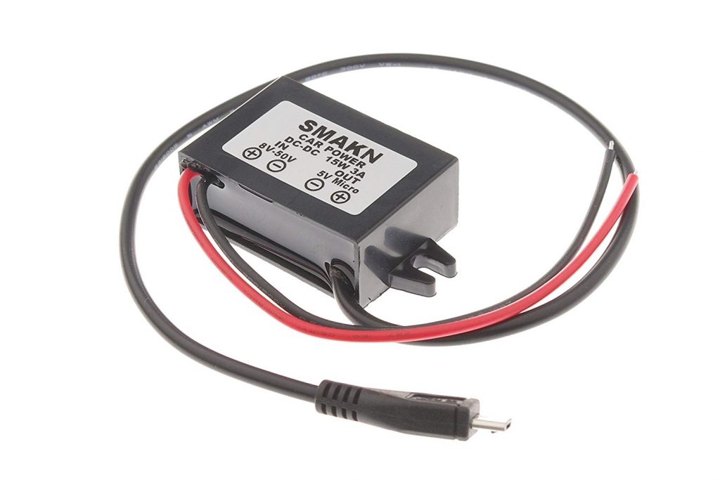
A DC-DC step down converter. Our battery is 12 volts, and the Raspberry Pi needs 5 volts through a micro USB plug. This will bring the voltage down and provides the micro USB plug needed by the Pi.
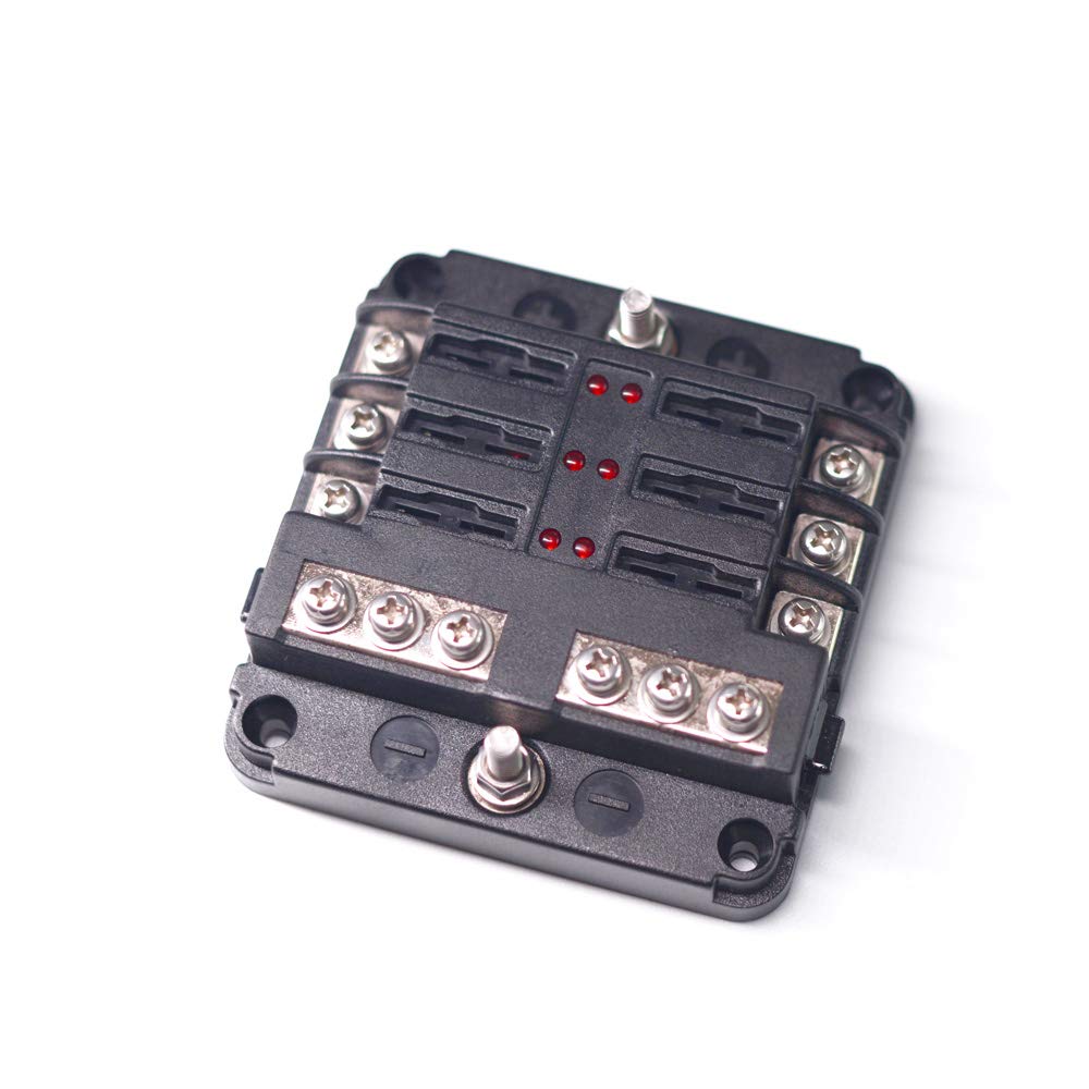
A small fuse block, just to make it the wiring little nicer.
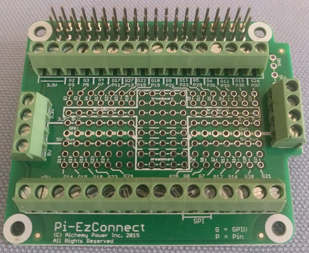
A pi-ezconnect hat. This just sits on top of the Pi, and breaks out all of the pins into easy to use wire terminals. Not completely necessary, but nicer than just sticking all of the wires into a breadboard.
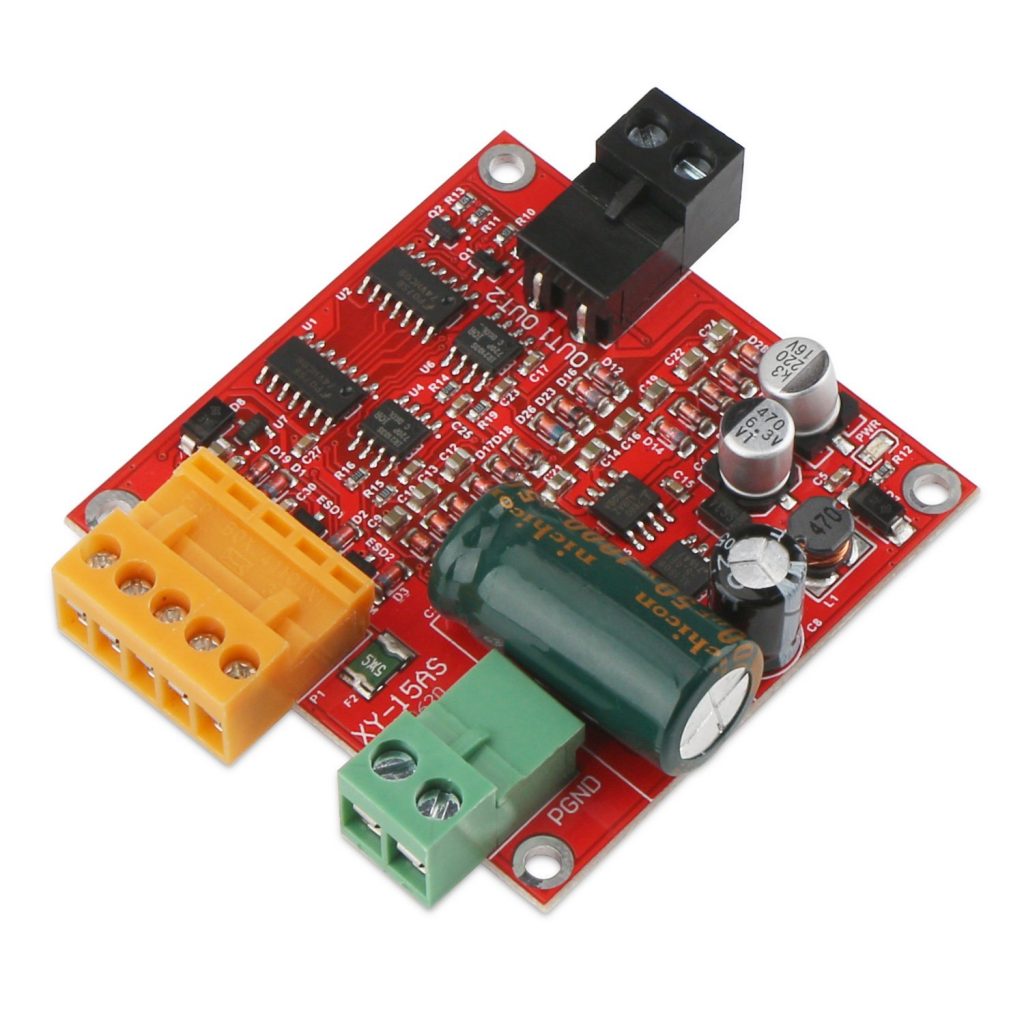
A motor controller board. This board lets us easily control the fan from the Pi. We’ll talk more about how to use it in the next post.
The Puzzle
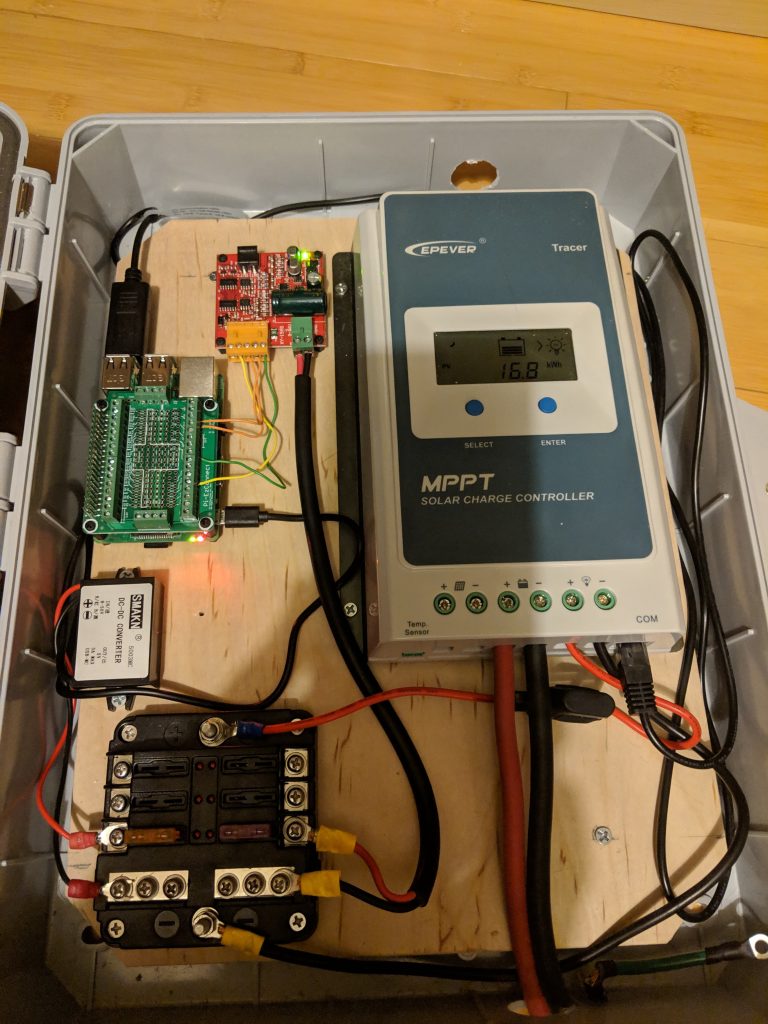
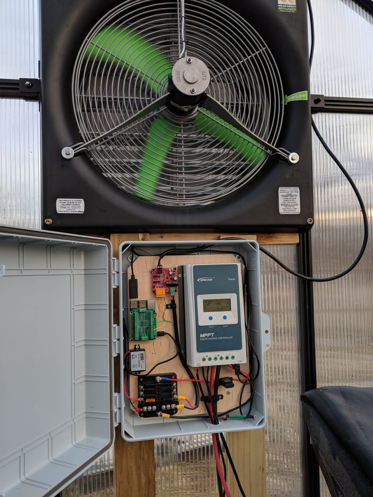
Above is my assembled product. The solar charger terminals are connected to the battery, and the load terminals are connected to the fuse panel (through an inline fuse on the positive wire.) The fuse panel is connected to both the DC-DC step down converter (which powers the Pi) and the motor controller. The Pi and the motor controller are both mounted to the wood using nylon stand offs. You can also see a USB to RS-485 adapter plugged in to the Pi, but ignore that. I ended up using something else, and I’ll explain it later.
Next, we mounted it to the actual greenhouse wall, under the fan:
I’ll talk more about the specific components, and how to make them work, in part 2.