Skip to content

Steve's Blog

  • About

Category: Pi Greenhouse Controller

Making an automated solar tracker

Posted on May 27, 2021 by Stephen Pape

Summary

For this project, I created a solar tracker to spin a solar panel towards the sun. Previously I had the panel propped up on the ground facing the south, but I thought it’d be more interesting if it could follow the sun all day.

Parts and basic construction

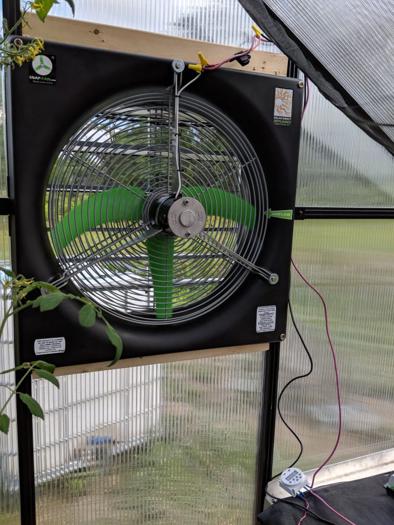
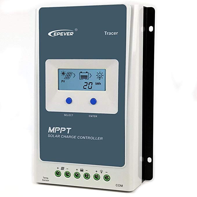
I purchased a 100W Solar Panel along with a pole mount. My father-in-law had a pole and two ball-bearing mounts that I used to allow the panel to spin while mounted to the post. They basically look like this, although I haven’t tested that one specifically. I also purchased a 12v worm gear motor which has a built in rotary encoder for position tracking. I already had a 12v battery and charger set up to power the greenhouse’s exhaust fan.

I drilled out a hole in the bottom of the post for the motor shaft to fit into, as well as another hole in the side of the shaft for a locking screw to lock the shaft in place.

Electronics

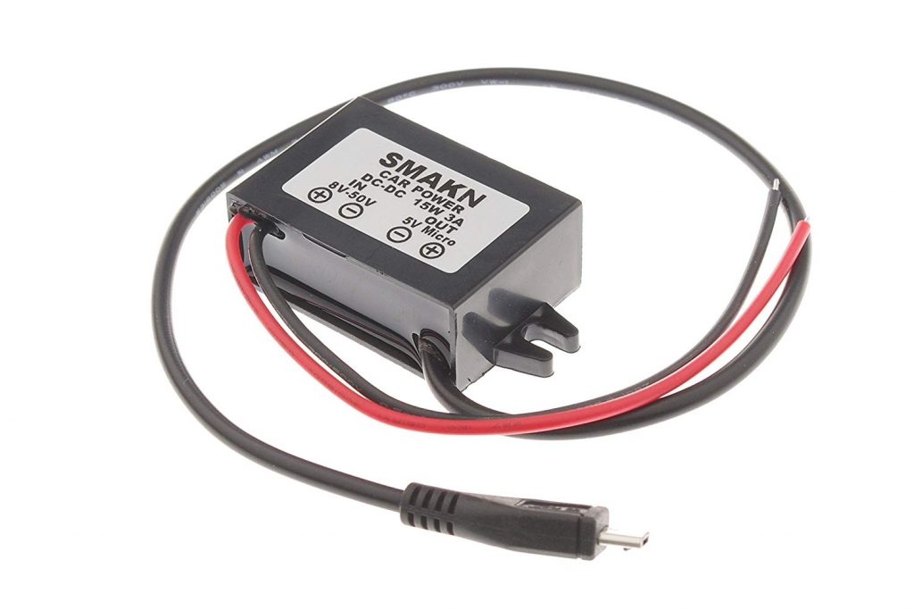
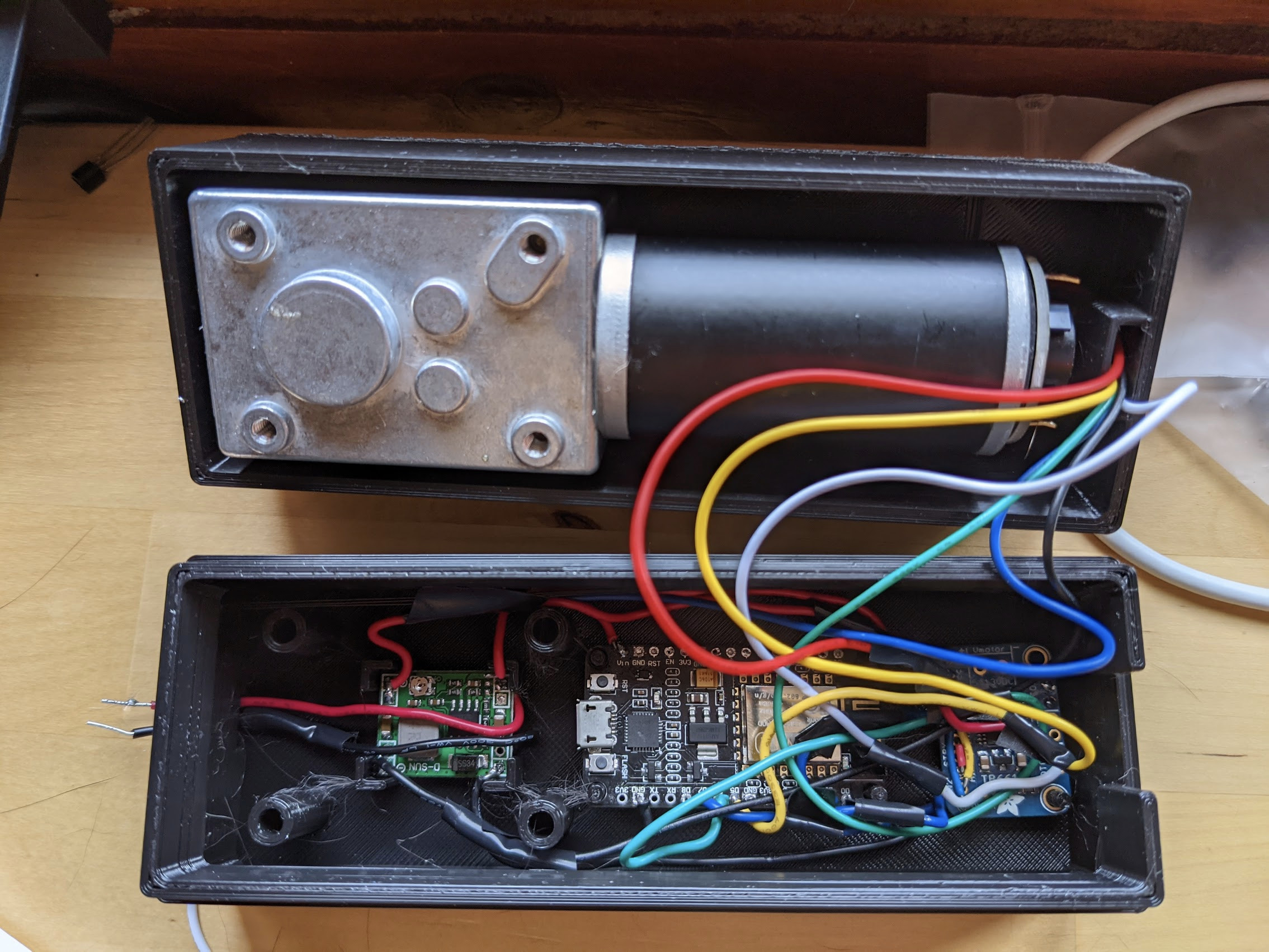
To test things out, I simply attached the motor to a vice on my desk. I wired up a 12v power supply for the motor, and used a voltage regular to drop down to 5v for the other components.

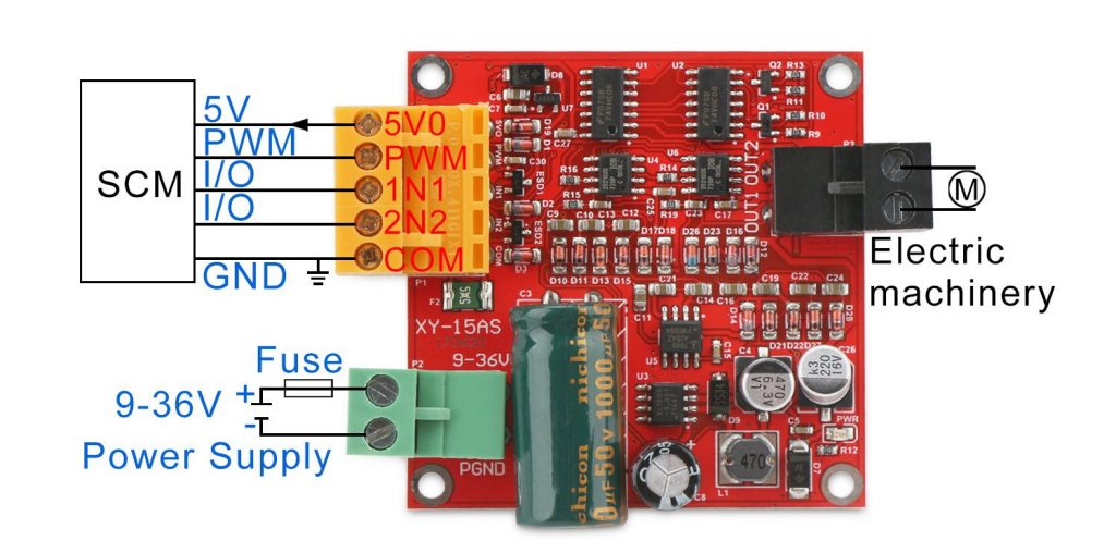
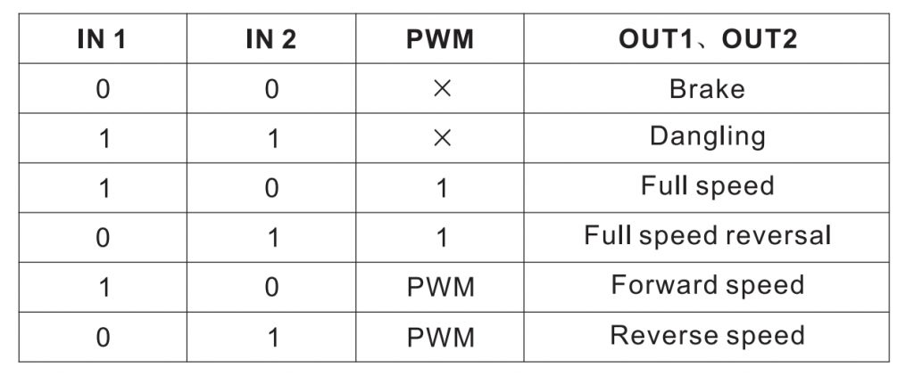
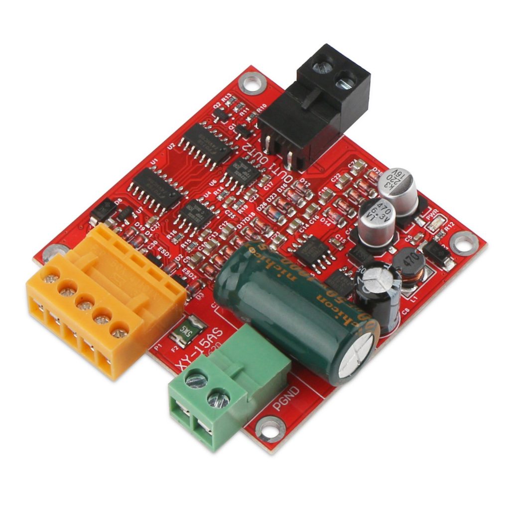
I used a TB6612 motor driver from AdaFruit to control the motor. Since it’s only rated at 1.2A per channel, and the motor says it can draw 2.4A, I bridged the two channels together (AIN1<->BIN1, AIN2<->BIN2, PWMA<->PWMB).

I used an ESP8266 to control everything. It has built-in WiFi, which is nice for pushing updates, getting feedback, and getting the current time to calculate the position of the sun.

Software

I programmed the ESP with the Arduino workbench. The basic idea is to use the motor encoder to track the direction of the panel.

Tracking Position

The motor I used is geared 522:1. That is, 522 spins of the motor are needed to turn the output shaft once. This provides a lot of torque and stops the mast from spinning freely while not powered. The encoders each emit 11 pules (ticks) per rotation, and there are two of them. Some simple math lets us determine pules per degree:

I used the RotaryEncoder library for Arduino to keep track of the motor’s current position. It handles an interrupt each time a pulse comes in from the motor’s encoder, and just counts up or down depending on the direction of spin.

Calibration

Since the encoder is not perfect, and no state is maintained after a power loss, we need a way to calibrate to a known position. To do this, I left a stop screw sticking out of the mast, preventing the motor from spinning past a certain point. The motor will spin backwards until the stop screw hits the wood. The ESP will detect that the motor is no longer making progress by tracking the rotary encoder, and will consider that the “zero” position.

Tracking the sun

Originally, I wanted to use photoresistors on each side of the panel to determine where to rotate the panel, but this had a couple of issues:

  • The ESP8266 only has one analog pin (solvable, we could multiplex the pin)
  • Photoresistors burn out if they’re left in the sun for too long

Instead, I used the SolarPosition Arduino library, as well as an Arduino NTPClient library. With these two libraries, and a known latitude and longitude, it’s easy to get the current solar azimuth.

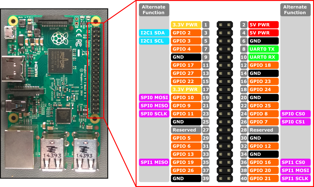
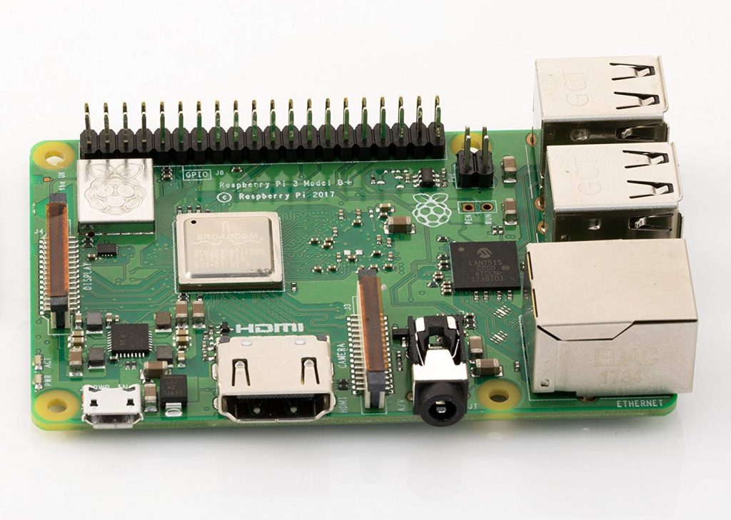
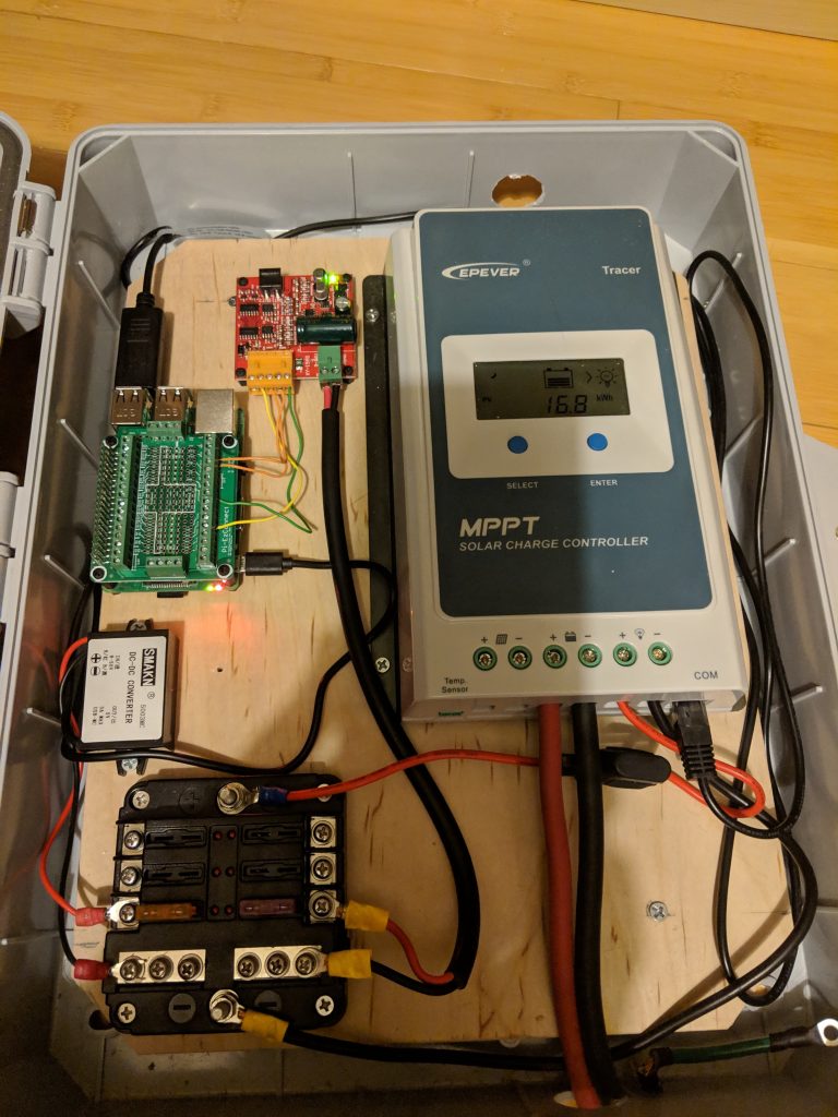
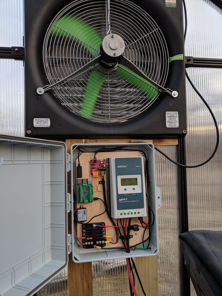
So that it doesn’t depend on the Internet, I set up the Raspberry Pi in the greenhouse as an access point, and made it a stratum 1 NTP server using a GPS module. The ESP connects to the Pi that is controlling my exhaust fan over WiFi, and uses its NTP service to get the current time.
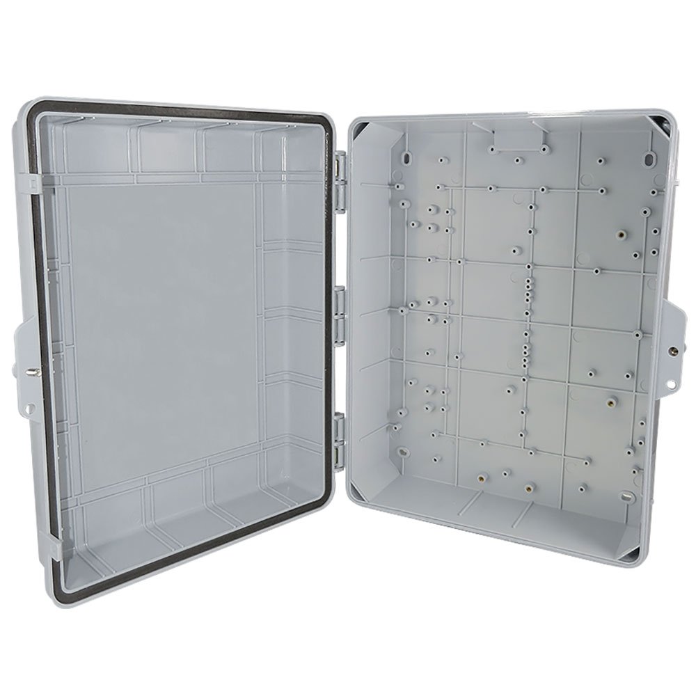
Making an enclosure

Next, I designed an enclosure in FreeCAD to house the motor and the electronics. I made a simple case that the motor can mount to, and a small board to house the electronics.

Next I 3D printed all of the pieces and assembled it:

Final Product

For the final touches, I coated the case with a spray on rubber insulator to prevent water from getting inside. After mounting everything and connecting power, the calibrated and spun into position:

Once the sun is below the horizon, the panel re-calibrates, leaving it facing east until the next morning.

Posted in Pi Greenhouse Controller, Projects, Solar TrackerLeave a comment

Raspberry Pi Greenhouse Controller – Part 2

Posted on April 30, 2019 by Stephen Pape

In part one, we put together the basic hardware for our solar-powered, Pi-controlled, greenhouse fan. This time, we’ll look at how to actually control the fan with Python on a Raspberry Pi.

Preparing the Raspberry Pi

There are plenty of resources online about getting up and running with a Pi, and that’s not really my objective here, but I’ll describe the high-level steps. I used the Raspbian Lite image, though other distributions can work as well. Installing it is just a matter of writing the image to an SD card, adding an empty ‘ssh’ file to the boot partition to turn on SSH, connecting it to Ethernet, and SSH’ing in. Once you’re connected, you can configure WiFi and unplug the cable.

The Motor Controller

Using the motor controller itself is pretty simple. The Pi controls it through pins on the yellow connector, it’s powered through the green connector, and it connects to the motor with the black connector.

The yellow connector has 5 pins: a 5V power supply (the Pi documentation says that we more than the 0.5a it can provide, so we can’t use it to power our Pi), three I/O pins, and a ground. The I/O pins are control the state of the motor as described in the following table:

By controlling the power supplied to IN1 and IN2, we can switch between braking, dangling (spinning freely), forwards, and backwards. For example, if IN1 and IN2 both have power, the motor is off, but if we turn on IN1 and turn off IN2, the fan will spin forward. The PWM pin, described more below, is used to control the speed, if used. If it’s not used, it can just be directly connected to power so that it’s effectively always set to full-speed.

Controlling the Fan State

The Raspberry Pi has a number of GPIO (general purpose input/output) pins. Essentially, each pin can be set to either input, where we can read if there is power on the pin, or output, where we can supply power on the pin (or not). GPIO on the Pi works at 3.3 volts, so you’ll need to make sure any devices you want to use can accept that voltage. Some require 5 volts, for example. The motor controller we’re using operates from 3-5 volts, so we’re good!

First, we’ll control the motor without speed control. I connected the motor controller’s IN1 and IN2 terminals to GPIO 12 and 16, respectively. Here is some Python using the wiringpi library to control the fan speed. Running it will cause the fan to spin forward at full speed.

#!/usr/bin/env python3
import wiringpi

fwd_pin = 12 # IN1
bwd_pin = 16 # IN2

def fwd():
    ''' 
    Make the motor spin forwards
    '''
    wiringpi.digitalWrite(fwd_pin, 1)
    wiringpi.digitalWrite(bwd_pin, 0)
    
def bwd():
    '''
    Make the motor spin backwards
    '''
    wiringpi.digitalWrite(fwd_pin, 0)
    wiringpi.digitalWrite(bwd_pin, 1)

def off():
    '''
    Turn of the motor (dangling)
    '''
    wiringpi.digitalWrite(fwd_pin, 1)
    wiringpi.digitalWrite(bwd_pin, 1)

def brake():
    '''
    Brake the motor
    '''
    wiringpi.digitalWrite(fwd_pin, 0)
    wiringpi.digitalWrite(bwd_pin, 0)

# Initialize the wiringPi library
wiringpi.wiringPiSetupGpio()

# Set both of our pins into output mode
wiringpi.pinMode(fwd_pin, 1)
wiringpi.pinMode(bwd_pin, 1)

# Turn on the fan
fwd()

Speed Control with PWM

Pulse-width modulation, briefly, controls the percentage of time that the pin is on, called the “duty cycle”. If the pin is high half the time, the duty cycle is 50%. The rate of these pulses is the frequency. You can picture this as a square wave. In this case, you don’t really need to know too much about PWM to use it.

The Raspberry Pi’s hardware can generate a PWM signal on GPIO 18, so that’s what we’ll use. We’ll connect GPIO 18 to the PWM input on the motor controller, and modify the above code. The motor controller’s manual suggests a 20khz signal, so we’ll aim for that. Here’s a snippet of code showing the PWM setup on the Pi:

pwm_pin = 18 # GPIO 18 supports hardware PWM
clock = 4    # Must be at least 2
max_range = 240  # 19200000 / 4 / 240 = 20000 (20khz)

# Just for verification
# It's not actually required that we calculate this.
freq = 19200000 / clock / max_range
print("Frequency:", freq)

# Configure PWM on our pin
wiringpi.pinMode(pwm_pin, 2)
wiringpi.pwmSetMode(wiringpi.PWM_MODE_MS)
wiringpi.pwmSetClock(clock)
wiringpi.pwmSetRange(max_range)

# Actually start the PWM signal at 50%
duty = 120
wiringpi.pwmWrite(pwmPin, duty)

The formula for calculating PWM frequency on the Pi is 19200000 / clock / range. The ‘range’ supplied is the maximum value that can supplied to pwmWrite(), so with the above code we can set the duty anywhere from 0 to 240. We’ve hardcoded the value 120, which will run the fan at 50%.

Here’s a more complete version, one that allows us to specify a percentage on the command line:

#!/usr/bin/env python3

import wiringpi
import sys

fwd_pin = 12
bwdPin = 16
pwmPin = 18
clock = 4    # Must be at least 2
max_range = 240  # 20khz

# Sanity checks
if clock < 2:
    print("Clock must be at least 2")
    exit(1)

if len(sys.argv) < 2:
    print("Usage: %s <Duty Percent>" % sys.argv[0])
    exit(1)

#
# Our control functions
#

def fwd():
    ''' 
    Make the motor spin forwards
    '''
    wiringpi.digitalWrite(fwd_pin, 1)
    wiringpi.digitalWrite(bwd_pin, 0)
    
def bwd():
    '''
    Make the motor spin backwards
    '''
    wiringpi.digitalWrite(fwd_pin, 0)
    wiringpi.digitalWrite(bwd_pin, 1)

def off():
    '''
    Turn of the motor (dangling)
    '''
    wiringpi.digitalWrite(fwd_pin, 1)
    wiringpi.digitalWrite(bwd_pin, 1)

def brake():
    '''
    Brake the motor
    '''
    wiringpi.digitalWrite(fwd_pin, 0)
    wiringpi.digitalWrite(bwd_pin, 0)

# Setup wiringpi and GPIO
wiringpi.wiringPiSetupGpio()
wiringpi.pinMode(fwd_pin, 1)
wiringpi.pinMode(bwd_pin, 1)

# Convert the requested percentage to
# a value between 0 and 'range' (240)
duty = int(max_range * (int(sys.argv[1]) / 100))

# If 0 is given, just turn it off.
if duty == 0:
    off()
    sys.exit(0)

# Configure PWM
wiringpi.pinMode(pwm_pin, 2)
wiringpi.pwmSetMode(wiringpi.PWM_MODE_MS)
wiringpi.pwmSetClock(clock)
wiringpi.pwmSetRange(max_range)
wiringpi.pwmWrite(pwm_pin, duty)

# Enable power
fwd()

Next time, we’ll add a temperature sensors to control the fan automatically.

Posted in Pi Greenhouse Controller, UncategorizedTagged dc motor, greenhouse, raspberry piLeave a comment

Raspberry Pi Greenhouse Controller – Part 1

Posted on April 28, 2019 by Stephen Pape

In this project, I’m using a solar panel to charge a 12v Marine/RV battery, which will power a Raspberry Pi and an exhaust fan for an off-the-grid greenhouse. My first goal was just to have an exhaust fan that keeps the temperature in the 80-85°F range, but it’d also be cool to add a web interface for climate and power stats, automatically control lights, water plants, etc. First, we’ll just start off with the exhaust fan.

The first thing we needed was a fan. I installed a 20″ DC Snap-Fan with the help of my father-in-law. It operates on 12 to 24 volts, with more speed as the voltage increases. To test it out, we just hooked it up to a small timer and a 12 volt battery. (The fan blades look strange in the photo because it’s running.) With the timer in place, the fan would stupidly run during the daytime, no matter the temperature. Time to make it smarter!

The Pieces

An enclosure. This is just a nice box to house all of our electrical components.

A Raspberry Pi to act as the brains. Mainly we need it for WiFi and GPIO (general purpose I/O), but they also have USB, HDMI, a GPU, and they’re fairly cheap.

A MPPT solar charge controller to charge the battery. This connects to a solar panel and a 12v RV battery, and keeps the battery charged. I like this one because it has an RS-485 port, so we can talk to it from the Pi.

A DC-DC step down converter. Our battery is 12 volts, and the Raspberry Pi needs 5 volts through a micro USB plug. This will bring the voltage down and provides the micro USB plug needed by the Pi.

A small fuse block, just to make it the wiring little nicer.

A pi-ezconnect hat. This just sits on top of the Pi, and breaks out all of the pins into easy to use wire terminals. Not completely necessary, but nicer than just sticking all of the wires into a breadboard.

A motor controller board. This board lets us easily control the fan from the Pi. We’ll talk more about how to use it in the next post.

The Puzzle

Above is my assembled product. The solar charger terminals are connected to the battery, and the load terminals are connected to the fuse panel (through an inline fuse on the positive wire.) The fuse panel is connected to both the DC-DC step down converter (which powers the Pi) and the motor controller. The Pi and the motor controller are both mounted to the wood using nylon stand offs. You can also see a USB to RS-485 adapter plugged in to the Pi, but ignore that. I ended up using something else, and I’ll explain it later.

Next, we mounted it to the actual greenhouse wall, under the fan:

I’ll talk more about the specific components, and how to make them work, in part 2.

Posted in Pi Greenhouse Controller, ProjectsTagged dc motor, electronics, greenhouse, raspberry piLeave a comment

Recent Posts

  • Making an automated solar tracker
  • Reverse Engineering a DVR camera system
  • Raspberry Pi Greenhouse Controller – Part 2
  • Raspberry Pi Greenhouse Controller – Part 1
  • Controlling a Ceiling Fan with HackRF – Part 1

Recent Comments

  • moad on Reverse Engineering a DVR camera system
  • Stephen Pape on Reverse Engineering a DVR camera system
  • Angel on Reverse Engineering a DVR camera system
  • Stephen Pape on Reverse Engineering a DVR camera system
  • John on Reverse Engineering a DVR camera system

Archives

  • May 2021
  • June 2020
  • April 2019
  • September 2015

Categories

  • DVR Hackery
  • Hampton Bay Fan Control
  • Pi Greenhouse Controller
  • Projects
  • Reverse Engineering
  • Solar Tracker
  • Technology
  • Uncategorized

Meta

  • Log in
  • Entries feed
  • Comments feed
  • WordPress.org
Proudly powered by WordPress | Theme: micro, developed by DevriX.