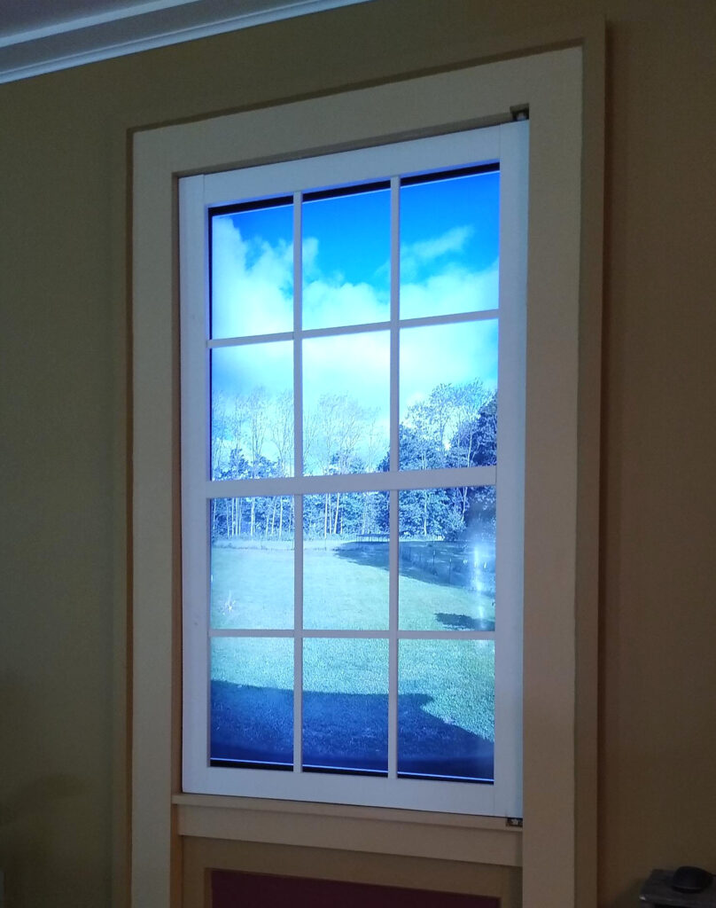
My father-in-law purchased a relatively inexpensive DVR camera system. He wanted to use is as an artificial window, by mounting a TV to the wall inside of a window frame. The problem is that there’s an annoying overlay in the corner, ruining the atmosphere.
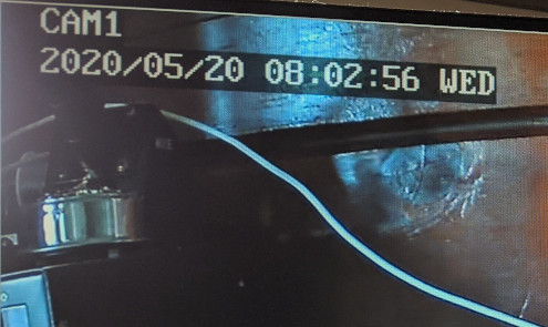
He had contacted the company, but was told that it couldn’t be disabled, and so he asked me to take a look.
System overview
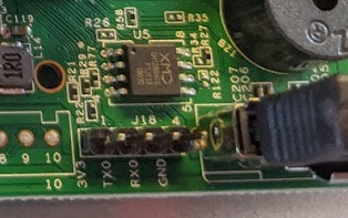
The system consists of a base station, which connects to the television. It also came with four wireless cameras. After opening the case and inspecting the board, I found a serial port, which I could use to communicate with the device.
I connected to the device over Ethernet, and looked around the web interface for camera options. I found that I could get rid of the “CAM1” part of the overlay by setting the camera’s name to be blank, but I couldn’t find anything to control the time and date portion. The only other interesting thing I found was a page to install a firmware update.
Getting the firmware
I searched online for a firmware update, and did end up finding one. The source web page was a little sketchy, but I examined it and found that it had a Linux kernel, a squashfs file system, and some other data. It did look correct, so I could have tried to make modifications to the update and upload it to the device. However, I was worried that if something went wrong, I’d have no way to recover. It’d be better to get access to the device itself, but I noted it as a possible option.
The next step was to wire up a serial connection to see if there was anything useful. I used a BusPirate, which is a USB device capable of speaking to several different bus types, and connected it to the serial pins:
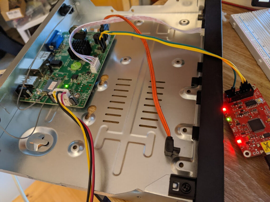
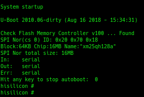
Powering on the device, I immediately saw a uBoot prompt. uBoot is a bootloader often used on embedded devices. By hitting the any key, I was able to stop the device from it’s normal startup and get to the bootloader prompt.
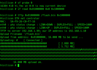
From the uBoot shell, I was able to load the entire contents of the flash chip into RAM, and use TFTP to copy it to my computer.
Analyzing the firmware
With the firmware file saved on my computer, I used binwalk to see what was inside of it. It turned out to be very similar to the firmware update I found online.

There’s a lot going on, but the squashfs sections, which contain the Linux filesystem, are where I suspected all of the interesting bits would be. There are two for some reason, but I started with the first.
To isolate the squashfs part of the image, I used dd.

Next, I unpacked it with unsquashfs. Finally, I was looking at the contents of the system!
Getting access to the live system
My initial goal was to get remote access while the system was running normally. The system had the telnetd binary installed, I just had to get it started up when the system boots. In the startup script /etc/init.d/S99, I noticed that it had been turned off.
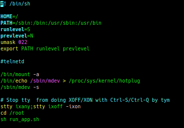
Turning it back on was easy enough, but I’d still need a password. I could have simply overwritten the contents of /etc/passwd, but first I figured I’d search online to see if anyone else had already cracked it.

It turns out that password is somewhat common; a Google search tells me that the password is “j1/_7sxw“. No need to overwrite it, since I know what it is.
Finally, I had to re-package my modifications and get them back onto the DVR. The first step was to repackage the squashfs file.
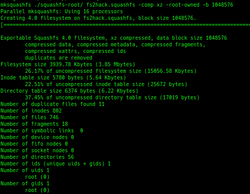
I then had to put a proper uImage header on the squashfs image via the mkimage command, and flashed it to the device:
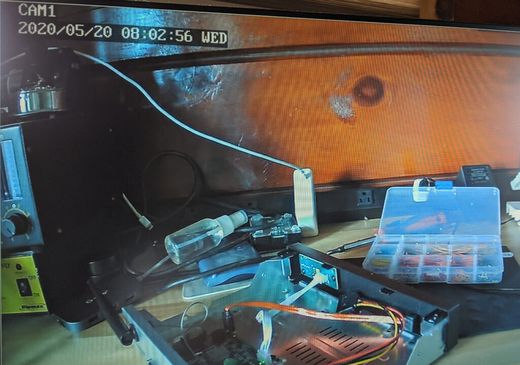
The offsets used are taken from binwalk. I transferred the modified image over TFTP into memory on the device, erased the original squashfs image, wrote the new data to flash, and rebooted it.
When it came back up, this time I was able to telnet to it. The credentials worked, and I now had remote access to the live system.

Pivoting to the cameras
The DVR had a second network interface, an internal-only network for the wireless cameras. It was easy to find the network name and password, and I probably could have connected with a regular PC at this point. Instead, I just used the DVR to hop to the cameras.
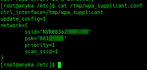
Using the arp command, I found a list of devices on the “internal” network. I only had one camera powered on at the time, and that was 172.20.14.33. I tried using telnet to get to the camera, using the same credentials as before, and they worked.
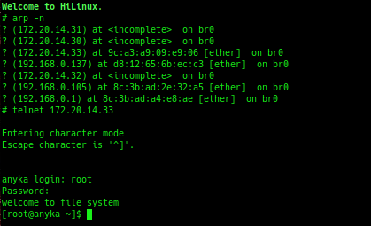
It turns out telnet was left enabled on the cameras, no hackery required! One interesting thing to note, the cameras themselves have Ethernet ports. If you can physically plug an Ethernet cable into the camera, you can skip all of the work I’d done up until this point, plug in a PC, and telnet to it that way. I still needed access to the DVR, anyway, for reasons that you’ll see later.
Looking at the camera’s filesystem, it has a single JFFS2 mount that caught my eye.
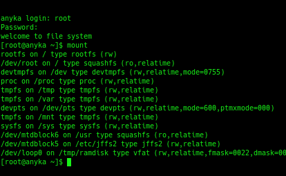
In that folder were configuration options:
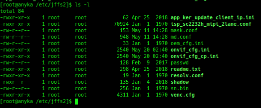
A quick glance through onvif_cfg.ini shows it has the settings we want to change.
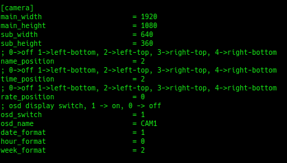
I changed name_position and time_position both to 0, disabling them. Since this file is on a writable partition, I simply saved the file and rebooted the camera. No uBoot flashing required.

That was it! The text is gone. For good measure, I copied out the camera’s filesystem to my PC using netcat with “tar cfp – /tmp | nc -w3 192.168.1.99 1234” on the device and “nc -l -p 1234 | tar xvfp –” on my PC. I didn’t end up actually needing anything from it, but I wanted to get everything out in case I wanted to make any future changes.
WiFi Overlay
At this point, I thought I was done. I even started repackaging the cameras, until I noticed this:
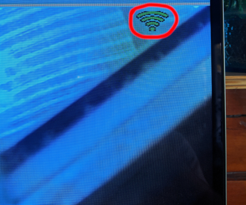
There’s a WiFi signal strength overlay in the upper right corner! Unfortunately, this one wasn’t going to be a simple configuration change. I determined that the DVR system itself adds the icon, not the camera. I located the relevant images on the DVR to try and get rid of them.
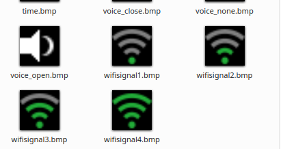
The first thing I tried was to replace the files with transparent images, and flashed the new image. The system rendered them as white boxes, which made it worse. Next I tried simply deleting the files. This caused the DVR system to crash. Alright, we’re doing it the hard way.
What’s rendering it?
The first step was to figure out what was rendering the WiFi signal graphics. To do this, I did a simple “grep” to for the filename:

The dvr_gui binary references the filename. Looking at the list of running processes confirms that it’s running. What this tells me is that the path to the image was hard-coded into the binary, and we’re going to need to patch it out.
Binary Analysis
I loaded dvr_gui in Ghidra, which is a software reverse-engineering framework developed by the NSA. Searching for the strings, I found this function that loads all of the WiFi images:
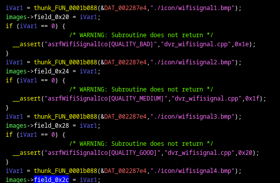
Next, I Googled for some error messages that I saw in the binary, like “1-bpp rect fill not yet implemented“. They turned out to be from SDL, an open-source library that I’m familiar with. This allowed me to make my first function label, SDL_SetError.
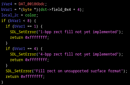
With SDL_SetError labeled, I could match error strings to the SDL source code, which allowed me to label SDL functions in the binary. The above image, for example, is code from SDL_FillRect. I went on a spree of labeling functions, creating structures, and setting proper arguments for SDL related code.
Now I knew exactly what was happening with those BMP files. They were opened with SDL_LoadBMP_RW and stored into an array. I tracked down where they were used, and found where it eventually calls SDL_UpperBlit to render to the screen. In the code below, FUN_0094034 is being passed one of the WiFi images, based on the signal strength, and then renders it.

Patching the binary
The next step was to get rid of it. I replaced the four bytes that execute the above function call with 0xE320F000, which is a NOP (no operation) for ARM processors. The result is that instead of calling the function that would render the image to the screen, it just moves down to the next instruction.
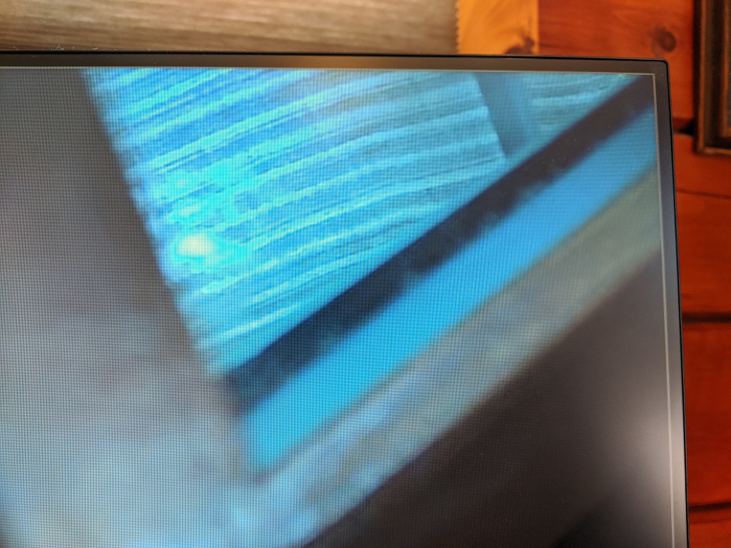
After replacing the binary in the squashfs image with my patched one, re-flashing the DVR, and booting it back up, the signal strength icon was gone!
Looking back at the WiFi images, the black part seems to get rendered as transparent. I think I could have replaced the WiFi images with all-black images. Oh well.
Conclusion
This ended up being a fun/small reverse engineering project, and there are other areas that I’d maybe like to explore someday, mainly security related.
It’s noteworthy that an attacker could plug Ethernet in to a camera, telnet to it using factory-set credentials, and find the WiFi password. It’d be interesting to try and tamper with the video feed. I’m also curious if I could exploit the DVR to get remote access without having to physically flash.
For now, though, the camera system is performing the job it was purchased for:
Wandering around the web and got here.
I’m just curious: at the WiFi overlay section, have you tried replacing those wifisignal*.bmp to pure black bmp files?
I mentioned that as something I believe would have worked; it does look like the black sections in the original images were rendered transparently. I was never able to test it out, though, because I did this for someone else and gave everything back right after I was finished. It only occurred to me as I was writing the blog post, haha.
Hi Stephen, amazing project!, How do you calculated the skip value for the dd command to extract the squashfs?. Cheers!
Hi Angel,
I got that value from the binwalk output: I used the skip value directly from binwalk and calculated the size by subtracting it from the start of the next section.
hi can you halp me to recovery password from bin file hikvison dvr