Summary
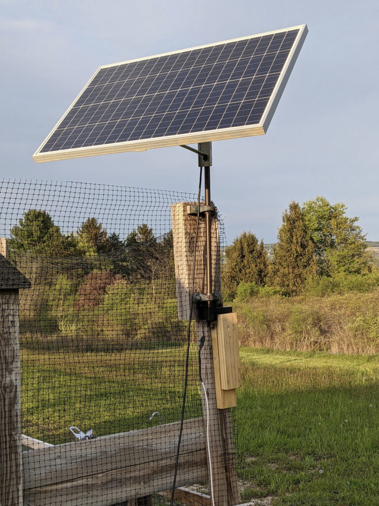
For this project, I created a solar tracker to spin a solar panel towards the sun. Previously I had the panel propped up on the ground facing the south, but I thought it’d be more interesting if it could follow the sun all day.
Parts and basic construction
I purchased a 100W Solar Panel along with a pole mount. My father-in-law had a pole and two ball-bearing mounts that I used to allow the panel to spin while mounted to the post. They basically look like this, although I haven’t tested that one specifically. I also purchased a 12v worm gear motor which has a built in rotary encoder for position tracking. I already had a 12v battery and charger set up to power the greenhouse’s exhaust fan.
I drilled out a hole in the bottom of the post for the motor shaft to fit into, as well as another hole in the side of the shaft for a locking screw to lock the shaft in place.
Electronics
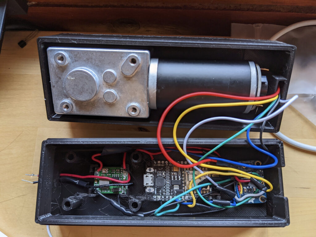
To test things out, I simply attached the motor to a vice on my desk. I wired up a 12v power supply for the motor, and used a voltage regular to drop down to 5v for the other components.
I used a TB6612 motor driver from AdaFruit to control the motor. Since it’s only rated at 1.2A per channel, and the motor says it can draw 2.4A, I bridged the two channels together (AIN1<->BIN1, AIN2<->BIN2, PWMA<->PWMB).
I used an ESP8266 to control everything. It has built-in WiFi, which is nice for pushing updates, getting feedback, and getting the current time to calculate the position of the sun.
Software
I programmed the ESP with the Arduino workbench. The basic idea is to use the motor encoder to track the direction of the panel.
Tracking Position
The motor I used is geared 522:1. That is, 522 spins of the motor are needed to turn the output shaft once. This provides a lot of torque and stops the mast from spinning freely while not powered. The encoders each emit 11 pules (ticks) per rotation, and there are two of them. Some simple math lets us determine pules per degree:

I used the RotaryEncoder library for Arduino to keep track of the motor’s current position. It handles an interrupt each time a pulse comes in from the motor’s encoder, and just counts up or down depending on the direction of spin.
Calibration
Since the encoder is not perfect, and no state is maintained after a power loss, we need a way to calibrate to a known position. To do this, I left a stop screw sticking out of the mast, preventing the motor from spinning past a certain point. The motor will spin backwards until the stop screw hits the wood. The ESP will detect that the motor is no longer making progress by tracking the rotary encoder, and will consider that the “zero” position.
Tracking the sun
Originally, I wanted to use photoresistors on each side of the panel to determine where to rotate the panel, but this had a couple of issues:
- The ESP8266 only has one analog pin (solvable, we could multiplex the pin)
- Photoresistors burn out if they’re left in the sun for too long
Instead, I used the SolarPosition Arduino library, as well as an Arduino NTPClient library. With these two libraries, and a known latitude and longitude, it’s easy to get the current solar azimuth.
So that it doesn’t depend on the Internet, I set up the Raspberry Pi in the greenhouse as an access point, and made it a stratum 1 NTP server using a GPS module. The ESP connects to the Pi that is controlling my exhaust fan over WiFi, and uses its NTP service to get the current time.
Making an enclosure
Next, I designed an enclosure in FreeCAD to house the motor and the electronics. I made a simple case that the motor can mount to, and a small board to house the electronics.

Next I 3D printed all of the pieces and assembled it:

Final Product
For the final touches, I coated the case with a spray on rubber insulator to prevent water from getting inside. After mounting everything and connecting power, the calibrated and spun into position:
Once the sun is below the horizon, the panel re-calibrates, leaving it facing east until the next morning.